Introduction
A battery indicator is an essential feature in any portable electronic project. Whether you’re building an Arduino project, an ESP32 IoT sensor, or a wearable device, knowing the battery voltage level helps prevent unexpected shutdowns. In this tutorial, we’ll build a battery voltage monitor using the MX1BM1 battery monitor module. This compact board allows you to measure LiPo / Li-ion battery levels (3.0–5.2V) safely with your microcontroller ADC (analog-to-digital converter).
We’ll cover:
- How the module works
- Circuit wiring with Arduino / ESP32
- Example code to measure battery voltage
- Applications of battery monitoring in IoT and electronics
What is the MX1BM1 Battery Voltage Monitor?
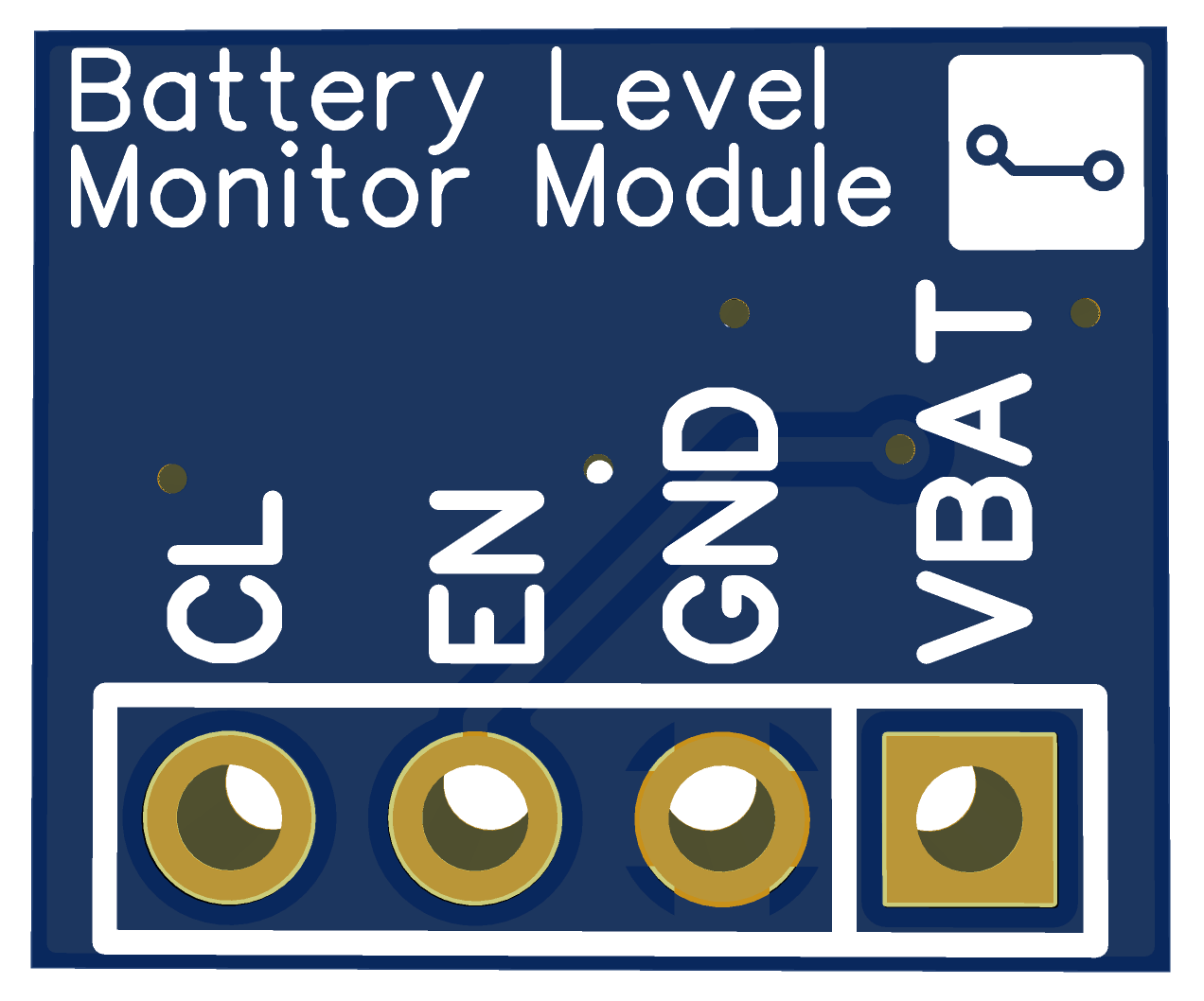
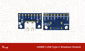
The MX1BM1 Battery Level Monitor Module is a small PCB designed to act as a battery indicator for microcontrollers. It works by scaling down the battery voltage using a resistive divider so that it can be safely read by 3.3V ADCs.
Key Features:
- Supports 3.0V to 5.2V input voltage (perfect for 1S LiPo / Li-ion)
- Outputs a scaled voltage for Arduino / ESP32 and other MCUs ADCs
- Enable pin for low-power operation (great for battery projects)
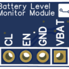
- Compact 12 × 10 mm board with standard 2.54mm pin header
- Includes a 10µF capacitor for stable voltage readings
Download the Gerber files here
Why Use a Battery Indicator in Your Projects?
Adding a battery indicator to your electronics project has several benefits:
- Prevent sudden shutdowns – get early warning before the battery dies
- IoT devices – report battery level to mobile apps or cloud dashboards
- Safe charging & protection – monitor low-voltage cut-off points
- Low-voltage – cuts-off system if voltage drops below defined value
- Diagnostics – test USB power levels or battery health
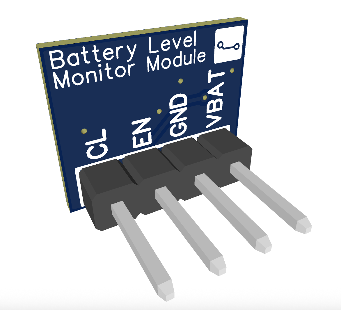
Pinout Description
Pin | Label | Function |
1 | VBAT | Connect to battery or input voltage (max 5.2V) |
2 | GND | Ground connection |
3 | EN | Enable control (active HIGH, 3.3V logic) |
4 | CL | Scaled analog voltage output to MCU ADC |
The EN pin allows you to turn the module on only when needed, reducing standby current in deep-sleep devices.
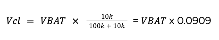
How it Works
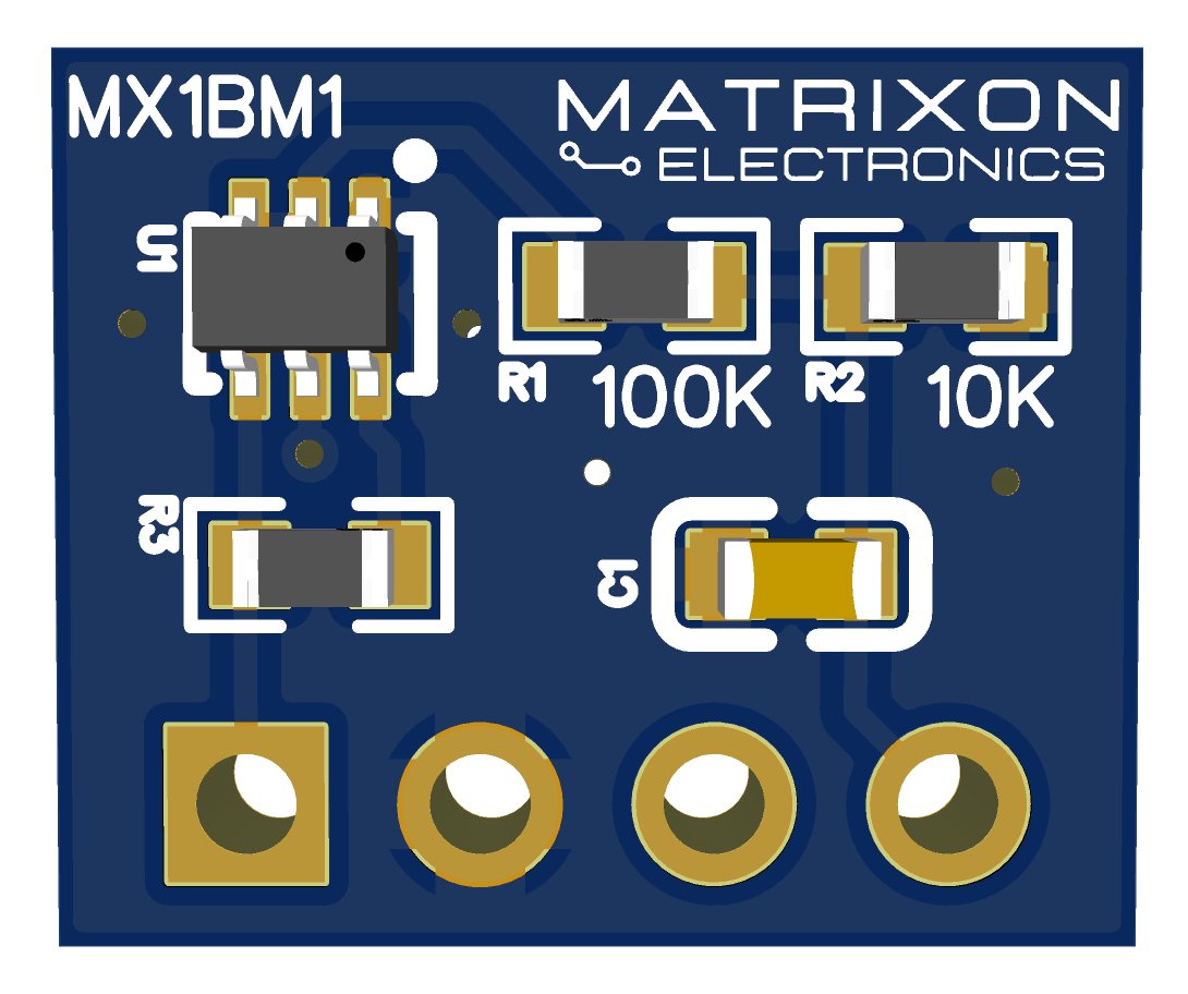
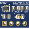
The MX1BM1 module uses a resistive voltage divider to scale down the input battery voltage:
This means:
Battery Voltage (VBAT) | Output Voltage (CL) |
3.0 V | 0.272 V |
3.7 V (Nominal LiPo) | 0.336 V |
4.2 V (Full charge) | 0.381 V |
5.0 V (USB) | 0.454 V |
5.2 V (VBAT max) | 0.472 V |
The microcontroller reads this scaled voltage through its ADC, then reconstructs the actual battery voltage using the known divider ratio.
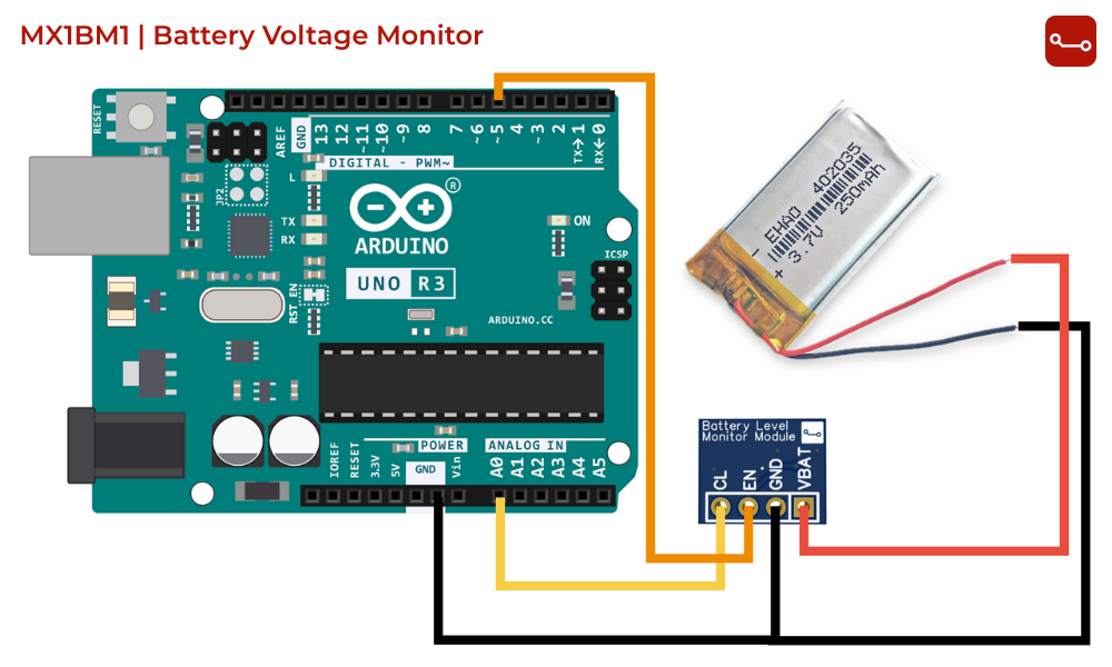
Circuit Setup – Battery Voltage Monitor with Arduino / ESP32
Components Required:
- MX1BM1 Battery Level Monitor Module
- Any MCU – Arduino Uno / STM32 board / ESP32
- 1S LiPo / Li-ion battery (3.0–4.2V)
- Jumper wires & breadboard
Connections (Arduino Example):
- VBAT → Battery +
- GND → Battery – & GND
- EN → D5 (or any GPIO)
- CL → A0 (ADC pin on arduino)
Example Arduino Code for Measure Battery Voltage
#define EN_PIN 5
#define CL_PIN A0
void setup() {
 pinMode(EN_PIN, OUTPUT);
 digitalWrite(EN_PIN, LOW);
 Serial.begin(9600);}
void loop() {
 digitalWrite(EN_PIN, HIGH);   // Enable module
 delay(5);                     // Wait for stable output
 int raw = analogRead(CL_PIN); // Read ADC value
 digitalWrite(EN_PIN, LOW);    // Disable module
  // Voltage divider: R1 = 100k, R2 = 10k
  // Divider ratio: CL = VBAT * (10 / 110) = VBAT * 0.0909
  // So, VBAT = CL / 0.0909
 float v_adc = raw * (3.3 / 4095.0);// ADC(assuming 12-bit ADC and 3.3Vref)
 float battery_voltage = v_adc / 0.0909; // Reconstruct battery voltage
 Serial.print("Battery Voltage: ");
 Serial.print(battery_voltage, 2);       // 2 decimal places
 Serial.println(" V");
 delay(1000);}
How the code works:
- MCU enables the module.
- Reads scaled voltage from CL.
- Converts it back to the actual battery voltage.
- Prints to the Serial Monitor.
- Module is disabled until the next reading.
Extensions & Ideas
- Add an OLED display to show battery percentage
- Send readings via Bluetooth Low Energy (BLE) or Wi-Fi
- Trigger a low-battery warning LED when voltage drops below 3.3V
- Use in remote IoT sensor nodes for smart battery diagnostics
Conclusion
With the MX1BM1 Battery Voltage Monitor Module, you can easily integrate a battery indicator into your Arduino or ESP32 projects. It’s compact, power-efficient, and ideal for IoT, wearables, and embedded systems.
Download the Gerber files here
Never let your devices die unexpectedly – add battery voltage monitoring today !
Battery Level Monitor Module Gerber Files – MX1BM1 | Battery Voltage Indicator PCB Design
Original price was: ₹499.00.₹359.00Current price is: ₹359.00.
A compact 4-pin module for monitoring battery voltage (3–5.2V) using an ADC, with enable function ideal for 1S LiPo and USB-powered projects.
Description
Disclaimer (Digital Product)
This product is a digital production pack, not a physical or assembled PCB. You will receive Gerber files, BOM, Schematics and documentation required to manufacture the PCB Module. No physical boards are shipped.
Download Product Datasheet: Download Now
Overview
The MX1BM1 Battery Level Monitor Module Gerber Files package provides a compact, low-power battery voltage monitoring PCB design for embedded systems, IoT devices, and battery-powered electronics. This board is designed to safely measure battery voltages ranging from 3.0V to 5.2V, making it suitable for 1S LiPo, Li-ion batteries, and USB-powered systems.
This battery level monitor PCB uses a precision voltage divider circuit combined with a MOSFET-based enable control, allowing developers to measure battery voltage only when required. This approach dramatically reduces standby current and makes the design ideal for deep-sleep applications and low-power battery management systems.
The module outputs a scaled analog voltage that can be directly connected to the ADC pin of popular microcontrollers such as ESP32, ESP8266, ESP32-C6, STM32, Arduino, and Raspberry Pi Pico. The design ensures ADC-safe voltage levels while maintaining measurement accuracy.
If you are searching for battery level indicator PCB Gerber files, battery monitoring circuit design, voltage divider PCB, or battery management design files, this module is a ready-to-manufacture solution.
Key Features
- Supports 3.0V to 5.2V battery input (VBAT)
- Optimized for 1S LiPo, Li-ion, and USB power sources
- Enable-controlled voltage divider for ultra-low power consumption
- Clean, stable ADC output using a 10 µF smoothing capacitor
- Scaled analog output safe for 3.3V ADC microcontrollers
- Standard 2.54mm 4-pin header for breadboard and jumper wire use
- Compact, space-saving PCB layout
- Designed for makers, hobbyists, engineers, and product developers
Applications
The MX1BM1 Battery Level Monitor Module is ideal for:
- Battery-powered IoT devices
- Wireless sensor nodes
- Low-power embedded systems
- Battery level reporting and telemetry
- Wearable electronics
- USB-powered diagnostic tools
- Battery cutoff and protection logic
- Prototyping battery management circuits
- Educational and DIY electronics projects
This PCB design is especially useful for developers building battery management systems, portable electronics, and energy-efficient microcontroller projects.
What You Will Receive (Digital Download)
This product pack will include:
- PCB Gerber Files
- Bill of Materials (BOM)
- Pick and Place (CPL)
- Example Arduino code for battery voltage reading
- Full product datasheet
- Documentation pack (README, License, T&C)
These files can be directly uploaded to PCB manufacturers such as JLCPCB, PCBWay, other manufacturers for fabrication.
Why Choose This Battery Level Monitor Module?
Unlike generic voltage divider circuits, the MX1BM1 design focuses on power efficiency, ADC safety, and real-world usability. The enable-controlled divider ensures minimal battery drain, making it suitable for production-grade designs, not just prototypes.
Whether you are a hobbyist looking for a reliable battery level indicator PCB or an engineer searching for ready-made battery monitoring Gerber files, this module saves design time and reduces risk.
Electrical Specifications
Input Voltage Range (VBAT): 3.0 V – 5.2 V
Supported Battery Types:
- 1S LiPo
- 1S Li-ion
- USB-powered sources
Output Signal: Scaled analog voltage (ADC-compatible)
Divider Ratio: ~0.0909 (VBAT → CL)
ADC Compatibility: Safe for 3.3 V ADC inputs
Enable Control: Yes (MOSFET-gated divider for low-power operation)
Standby Current: Near-zero when disabled (dependent on MOSFET leakage)
Pinout Description
| Pin | Label | Function |
| 1 | VBAT | Connect to battery or input voltage (max 5.2V) |
| 2 | GND | Ground connection |
| 3 | EN | Enable control (active HIGH, 3.3V logic) |
| 4 | CL | Scaled analog voltage output to MCU ADC |
PCB Layout & Dimensions
| Parameter | Value |
| Board Size | 12mm x 10mm |
| Layers | 2 |
| Components Placement | Top layer (Single side) |
| Pin Pitch | 2.54mm |
| Pin Header | 1×4 Male |
Related products
 Add to WishlistAdd to Wishlist


Reviews
There are no reviews yet.