Introduction
If you’ve ever looked at a circuit diagram or datasheet, you’ve probably seen terms like VCC, VDD, VSS, and GND. These labels define how power is distributed in an electronic circuit — but what do they really mean?
In this post, we’ll clearly explain the differences between these common voltage and power reference terms used in electronics, microcontrollers, and semiconductors, so you’ll never be confused again.
What Do VCC, VDD, VSS, and GND Mean?
| Term | Full Form | Typical Meaning | Common Use |
|---|---|---|---|
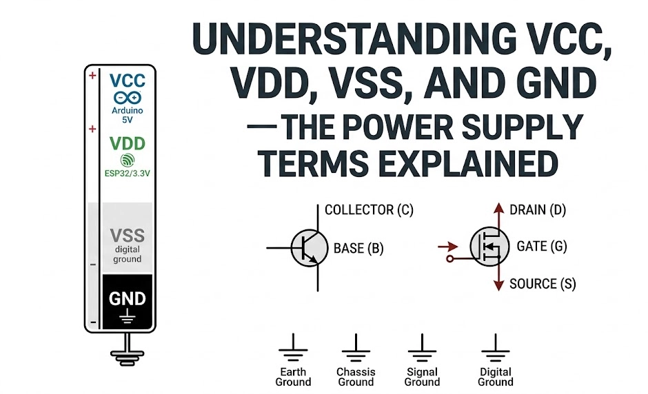
| VCC | Voltage at the Common Collector | Positive power supply for bipolar (BJT) circuits | Arduino, analog ICs |
| VDD | Voltage at the Drain | Positive power supply for FET-based circuits | ESP32, STM32, digital ICs |
| VSS | Voltage at the Source | Ground (negative) in FET-based circuits | Digital ICs, CMOS logic |
| GND | Ground | Circuit reference point (0V) | Every electronic circuit |
1. VCC – Voltage Common Collector
The term VCC comes from Bipolar Junction Transistor (BJT) logic families.
In BJT-based circuits, the collector is connected to the positive supply, so VCC simply means the positive voltage supply line.
Examples:
- 5V VCC in Arduino and TTL circuits
- 3.3V VCC in low-power modules and microcontrollers
2. VDD – Voltage Drain to Drain
VDD originated from MOSFET (Field-Effect Transistor) design. In a MOSFET, the drain is typically connected to the positive supply. Therefore, VDD refers to the positive power rail in CMOS or FET logic systems.
Examples:
- ESP32, STM32, and Raspberry Pi boards often use VDD = 3.3V
- Digital ICs with FET transistors (e.g., logic gates, microcontrollers)
3. VSS – Voltage Source to Source
VSS is the complement of VDD. It refers to the voltage at the source terminal of MOSFETs, which is usually ground or 0V.
In many digital systems, VSS is synonymous with GND, but its label is based on transistor-level design.
Examples:
- FET-based ICs: VDD = +3.3V, VSS = 0V
- Memory chips, microcontrollers, and CMOS logic devices
4. GND – Ground
GND (Ground) is the reference point in an electrical circuit. It may or may not be connected to Earth ground, but it’s always considered 0V in circuit operation.
There are three types of grounds in electronics:
- Earth Ground — connected to the physical ground (for safety)
- Chassis Ground — connected to the metal body or frame of a device
- Signal Ground — used as voltage reference for low-voltage circuits
Comparing VCC, VDD, VSS, and GND
| Parameter | BJT Circuit | FET Circuit | Common Usage |
|---|---|---|---|
| Positive Voltage | VCC | VDD | Power Supply + |
| Negative / Ground | GND | VSS | Reference (0V) |
| Example IC | 74HC04, LM358 | ESP32, STM32 | Both Analog + Digital |
| Typical Voltage | 3.3V / 5V / 12V | 3.3V / 5V | Varies by device |
Why Different Terms Exist
These naming conventions were created to match the transistor technology used inside integrated circuits:
- BJT-based logic → uses VCC / GND
- MOSFET-based logic → uses VDD / VSS
- Mixed-signal ICs may use both depending on section type
Today, most modern ICs use VDD (for positive) and VSS (for ground), but VCC and GND remain common in general electronics.
Example: ESP32 Power Pin Naming
| Pin Label | Function |
|---|---|
| 3V3 / VDD | Main 3.3V power rail |
| GND / VSS | Ground reference |
| VIN / VCC | Input supply (e.g., from USB or external battery) |
So if you’re powering your ESP32 with a LiPo battery through the MX1BM1 -Battery Level Monitor Module, connect:
- VBAT → VIN (or VCC)
- GND → GND (or VSS)
Quick Tips for Beginners
- Treat VCC and VDD as “+ voltage supply.”
- Treat VSS and GND as “0V reference.”
- Always check your datasheet pinout before wiring — naming conventions differ across ICs.
- Some devices have multiple grounds (analog GND, digital GND). Keep them isolated if specified.
Conclusion
Understanding the difference between VCC, VDD, VSS, and GND is essential for reading schematics and connecting power correctly.
These voltage references might look confusing, but they all define how current flows and where “zero volts” lies in your circuit.
Explore more hardware blogs at Matrixon Electronics – where we simplify electronics one concept at a time!